Arquitectura de computadoras
Proponer la selección de ciertos equipos (arquitecturas computacionales) según los requerimientos de funcionalidad, rendimiento y costo, en laboratorios.
Realización de un procesador
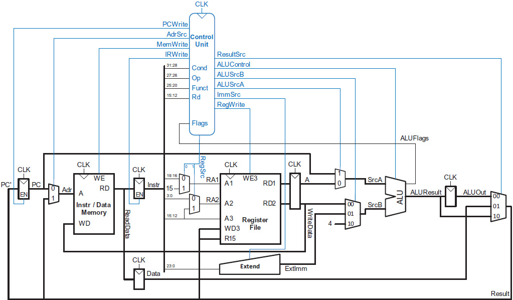
Dividimos nuestras microarquitecturas en dos partes interactivas: la ruta de datos y la unidad de control. La ruta de datos opera en palabras de datos. Contiene estructuras como memorias, registros, ALU y multiplexores. Estamos implementando la arquitectura ARM de 32 bits, por lo que usamos una ruta de datos de 32 bits.
La unidad de control recibe la instrucción actual de la ruta de datos y le dice a la ruta de datos cómo ejecutar esa instrucción. Específicamente, la unidad de control produce señales de selección de multiplexor, habilitación de registro y escritura de memoria para controlar el funcionamiento de la ruta de datos.
ARM – processor
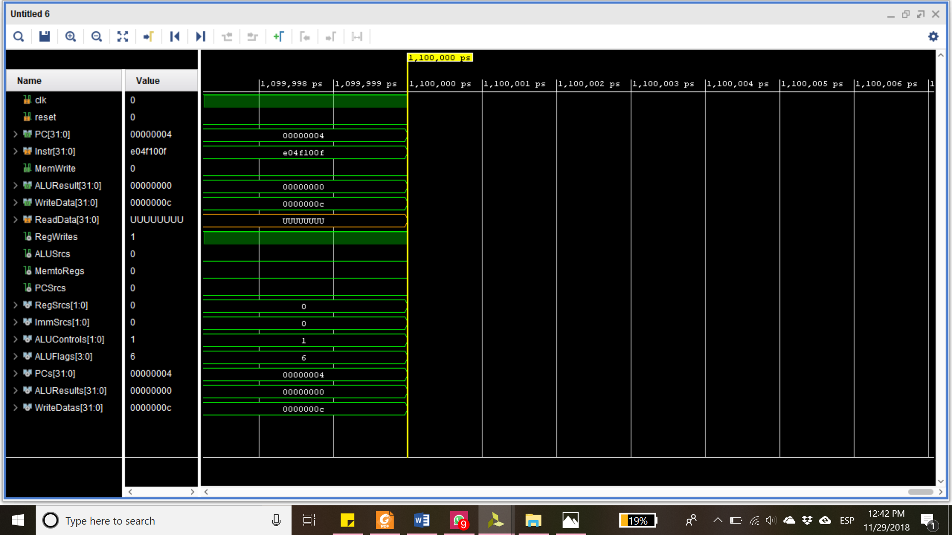
Descripción: Nuestra única entrada es la instrucción ya que la función del procesador es procesar instrucciones.
- PC: devuelve el número de la siguiente instrucción a ejecutar
- Instr: contiene la instrucción a ejecutar
- MemWrite: determina si se va a escribir en la memoria
- ALUResult: WriteData: devuelve el resultado del ALU y el Data a escribir en la memoria
- ReadData: es una entrada que muestra un dato de la memoria si la instrucción lo requiere
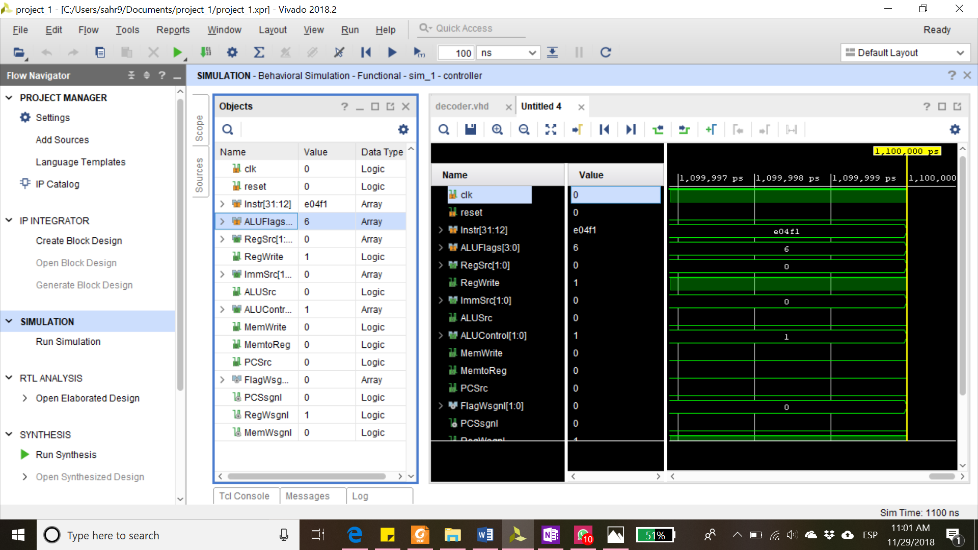
Controlador
Descripción: El controlador es el que controla precisamente al datapath. Decodifica la instrucción para habilitar los componentes del datapath y utiliza un conditional check para verificar las condiciones de la instrucción, así como la lectura y escritura de datos en la memoria.
- Instr: contiene la instrucción a decodificar
- ALUFlags: contiene las flags que devuelve el ALU
- RegSrc: Devuelve el registro origen
- RegWrite: habilita la escritura en los registros del regFile
- ImmSrc: Determina el tipo de operación (procesamiento de datos, memoria o branches)
- ALUSrc: Habilita la entrada de datos al ALU
- ALUControl: Determina el tipo de operación a realizar del ALU
- MemWrite: Habilita la escritura en la memoria
- MemtoReg: Permite escribir en un registro lo que hay en la memoria
- PCSrc: Devuelve el PC del conditionalcheck
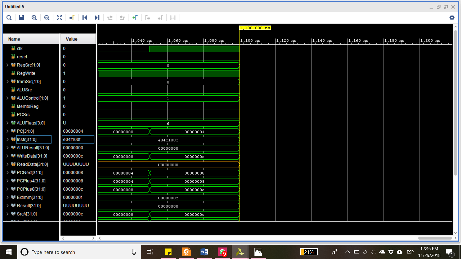
Datapath
Descripción: determina el camino que los datos van a tomar y manda habilita los componentes según las señales del controlador.
- RegSrc: determina el tipo de operación para el regFile
- RegWrite: habilita escribir en los registros
- ImmSrc: determina el tipo de operación para la extensión (proceso de datos, memoria, branches)
- ALUSrc: coloca inmediato o no
- ALUControl: tipo de operación del ALU
- MemtoReg: si se escribe lo de la memoria en el resultado
- PCSrc: dice cual será la siguiente instrucción
- ReadData: es la salid del data memory
- PC: Es el número de instrucción
- Instr: la instrucción PC
- ALUResult, WriteData: resultado del ALU, writeData es lo que se escribirá en la memoria
- ALUFlags: salida de las banderas del ALU
Archivo de registro
Descripción: El circuito de registro consiste en multiples entradas tales como las entradas de registro de intrsucciones que tienen 4 bits, entradas de registro de 32 bits, un clk para la activación de dicho componente, el cual se puene inicializar en cero o uno, y dos salidas de registros de 32 bits.
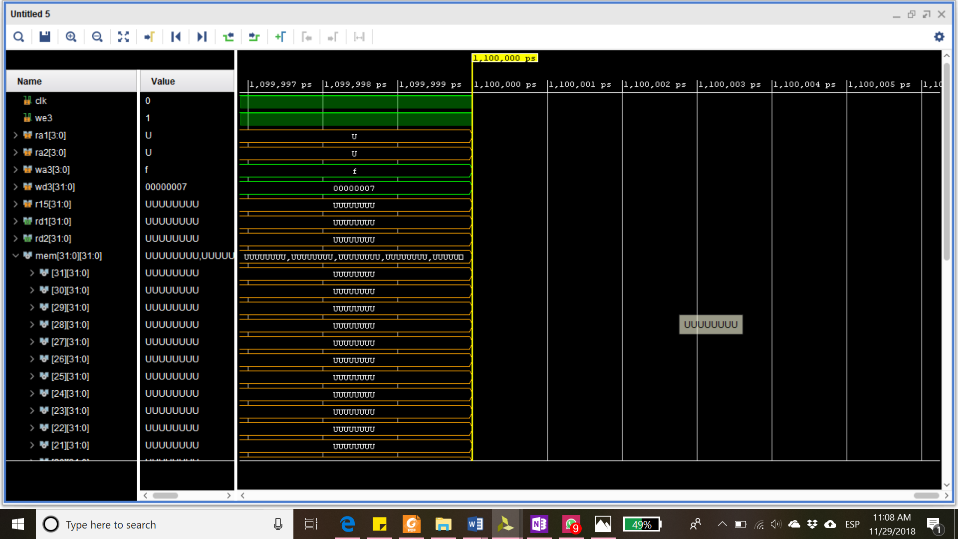
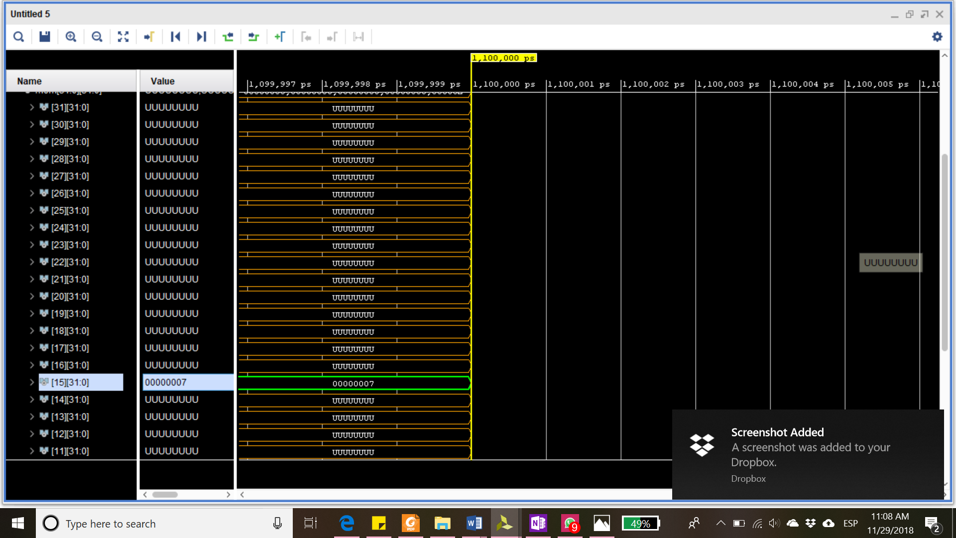
Habilitamos la escritura y escribimos un “7” en el Registro 15 como se muestra a continuación. We3 habilita la escritura, wa3 es el registro destino y wd3 es la data a escribir.
Extensión
Descripción: El circuito de extensión consiste en dos entradas, la instrucción de 24 bits e Inmediato de Origen de 2 bits (00,01,10) y una salida llamada extensión final de 32 bits.
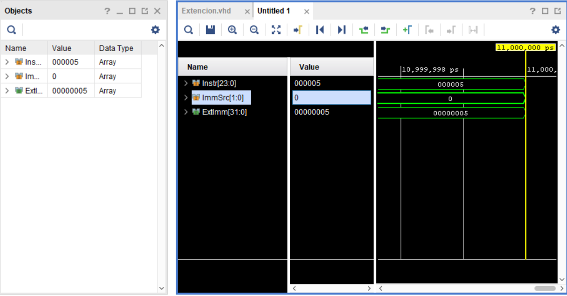
Tenemos en el immSrc un “00” que nos indica una operación de procesamiento de datos. La instrucción del bit 0 al 23 nos indica que el inmediato es un 5. Por lo tanto la extensión nos devuelve un la instrucción del bit 0 al 7 con 24 “0” concatenados.
Códigos
ARM
library IEEE;
use IEEE.STD_LOGIC_1164.ALL;
entity arm is
--  Port ( );
    port(clk, reset: in STD_LOGIC;
    PC: out STD_LOGIC_VECTOR(31 downto 0);
    Instr: in STD_LOGIC_VECTOR(31 downto 0);
    MemWrite: out STD_LOGIC;
    ALUResult, WriteData: out STD_LOGIC_VECTOR(31 downto 0);
    ReadData: in STD_LOGIC_VECTOR(31 downto 0));
end arm;
architecture struct of arm is
    component controller
        port(clk, reset: in STD_LOGIC;
        Instr: in STD_LOGIC_VECTOR(31 downto 12);
        ALUFlags: in STD_LOGIC_VECTOR(3 downto 0);
        RegSrc: out STD_LOGIC_VECTOR(1 downto 0);
        RegWrite: out STD_LOGIC;
        ImmSrc: out STD_LOGIC_VECTOR(1 downto 0);
        ALUSrc: out STD_LOGIC;
        ALUControl: out STD_LOGIC_VECTOR(1 downto 0);
        MemWrite: out STD_LOGIC;
        MemtoReg: out STD_LOGIC;
        PCSrc: out STD_LOGIC);
    end component;
    component datap
        port(clk, reset: in STD_LOGIC;
        RegSrc: in STD_LOGIC_VECTOR(1 downto 0);
        RegWrite: in STD_LOGIC;
        ImmSrc: in STD_LOGIC_VECTOR(1 downto 0);
        ALUSrc: in STD_LOGIC;
        ALUControl: in STD_LOGIC_VECTOR(1 downto 0);
        MemtoReg: in STD_LOGIC;
        PCSrc: in STD_LOGIC;
        ALUFlags: out STD_LOGIC_VECTOR(3 downto 0);
        PC: buffer STD_LOGIC_VECTOR(31 downto 0);
        Instr: in STD_LOGIC_VECTOR(31 downto 0);
        ALUResult, WriteData: buffer STD_LOGIC_VECTOR(31 downto 0);
        ReadData: in STD_LOGIC_VECTOR(31 downto 0));
    end component;
signal RegWrites, ALUSrcs, MemtoRegs, PCSrcs: STD_LOGIC;
signal RegSrcs, ImmSrcs, ALUControls: STD_LOGIC_VECTOR (1 downto 0);
signal ALUFlags: STD_LOGIC_VECTOR(3 downto 0);
signal PCs, ALUResults, WriteDatas: STD_LOGIC_VECTOR(31 downto 0);
begin
cont: controller port map(clk, reset, Instr(31 downto 12), ALUFlags, RegSrcs, RegWrites, ImmSrcs, ALUSrcs, ALUControls, MemWrite, MemtoRegs, PCSrcs);
dp: datap port map(clk, reset, RegSrcs, RegWrites, ImmSrcs, ALUSrcs, ALUControls, MemtoRegs, PCSrcs, ALUFlags, PCs, Instr, ALUResults, WriteDatas, ReadData);
--RegWrite<=RegWritesgnl;
ALUResult<=ALUResults;
--ReadData<=MemWritesgnl;
--PCSrc<=PCSrcsgnl;
PC<=PCs;
WriteData<=WriteDatas;
end;
Controller
library IEEE;
use IEEE.STD_LOGIC_1164.ALL;
entity controller is
--  Port ( );
    port(clk, reset: in STD_LOGIC;
    Instr: in STD_LOGIC_VECTOR(31 downto 12);
    ALUFlags: in STD_LOGIC_VECTOR(3 downto 0);
    RegSrc: out STD_LOGIC_VECTOR(1 downto 0);
    RegWrite: out STD_LOGIC;
    ImmSrc: out STD_LOGIC_VECTOR(1 downto 0);
    ALUSrc: out STD_LOGIC;
    ALUControl: out STD_LOGIC_VECTOR(1 downto 0);
    MemWrite: out STD_LOGIC;
    MemtoReg: out STD_LOGIC;
    PCSrc: out STD_LOGIC);
end controller;
architecture struct of controller is
    component decoder
        port(Op: in STD_LOGIC_VECTOR(1 downto 0);
        Funct: in STD_LOGIC_VECTOR(5 downto 0);
        Rd: in STD_LOGIC_VECTOR(3 downto 0);
        FlagW: out STD_LOGIC_VECTOR(1 downto 0);
        PCS, RegW, MemW: out STD_LOGIC;
        MemtoReg, ALUSrc: out STD_LOGIC;
        ImmSrc, RegSrc: out STD_LOGIC_VECTOR(1 downto 0);
        ALUControl: out STD_LOGIC_VECTOR(1 downto 0));
    end component;
    component conditional
        port(clk, reset: in STD_LOGIC;
        Cond: in STD_LOGIC_VECTOR(3 downto 0);
        ALUFlags: in STD_LOGIC_VECTOR(3 downto 0);
        FlagW: in STD_LOGIC_VECTOR(1 downto 0);
        PCS, RegW, MemW: in STD_LOGIC;
        PCSrc, RegWrite: out STD_LOGIC;
        MemWrite: out STD_LOGIC);
    end component;
signal FlagWsgnl: STD_LOGIC_VECTOR(1 downto 0);
signal PCSsgnl, RegWsgnl, MemWsgnl: STD_LOGIC;
begin
dec: entity work.decoder port map(Op=>Instr(27 downto 26), Funct=>Instr(25 downto 20), Rd=>Instr(15 downto 12), FlagW=>FlagWsgnl, PCS=>PCSsgnl, RegW=>RegWsgnl, MemW=>MemWsgnl, MemtoReg=>MemtoReg, ALUSrc=>ALUSrc, ImmSrc=>ImmSrc, RegSrc=>RegSrc, ALUControl=>ALUControl);
cl: entity work.conditional port map(clk=>clk, reset=>reset, Cond=>Instr(31 downto 28), ALUFlags=>ALUFlags, FlagW=>FlagWsgnl, PCS=>PCSsgnl, RegW=>RegWsgnl, MemW=>MemWsgnl, PCSrc=>PCSrc, RegWrite=>RegWrite, MemWrite=>MemWrite);
end;
Datapath
library IEEE;
use IEEE.STD_LOGIC_1164.ALL;
entity datap is
--  Port ( );
port(clk, reset: in STD_LOGIC;
RegSrc: in STD_LOGIC_VECTOR(1 downto 0);
RegWrite: in STD_LOGIC;
ImmSrc: in STD_LOGIC_VECTOR(1 downto 0);
ALUSrc: in STD_LOGIC;
ALUControl: in STD_LOGIC_VECTOR(1 downto 0);
MemtoReg: in STD_LOGIC;
PCSrc: in STD_LOGIC;
ALUFlags: out STD_LOGIC_VECTOR(3 downto 0);
PC: buffer STD_LOGIC_VECTOR(31 downto 0);
Instr: in STD_LOGIC_VECTOR(31 downto 0);
ALUResult, WriteData: buffer STD_LOGIC_VECTOR(31 downto 0);
ReadData: in STD_LOGIC_VECTOR(31 downto 0));
end datap;
architecture struct of datap is
component alu
generic(M: integer :=32);
Port (a,b : in STD_LOGIC_VECTOR (M-1 downto 0);
control : in STD_LOGIC_VECTOR (1 downto 0);
result : out STD_LOGIC_VECTOR (M-1 downto 0);
flags : out STD_LOGIC_VECTOR (3 downto 0));
end component;
component regfile
port(clk: in STD_LOGIC;
we3: in STD_LOGIC;
ra1, ra2, wa3: in STD_LOGIC_VECTOR(3 downto 0);
wd3, r15: in STD_LOGIC_VECTOR(31 downto 0);
rd1, rd2: out STD_LOGIC_VECTOR(31 downto 0));
end component;
component adder is
generic(N: integer := 32);
port(a, b: in STD_LOGIC_VECTOR(N-1 downto 0);
s: out STD_LOGIC_VECTOR(N-1 downto 0);
cin: in STD_LOGIC;
cout: out STD_LOGIC);
end component;
component immediate
port(Instr: in STD_LOGIC_VECTOR(23 downto 0);
ImmSrc: in STD_LOGIC_VECTOR(1 downto 0);
ExtImm: out STD_LOGIC_VECTOR(31 downto 0));
end component;
component flopenr generic(width: integer:= 4);
port(clk, reset, en: in STD_LOGIC;
d: in STD_LOGIC_VECTOR(width-1 downto 0);
q: out STD_LOGIC_VECTOR(width-1 downto 0));
end component;
component mux21 generic (N: integer:= 4);
Port (c1, c2 : in STD_LOGIC_VECTOR (N-1 downto 0);
s : in STD_LOGIC;
z : out STD_LOGIC_VECTOR (N-1 downto 0));
end component;
signal PCNext, PCPlus4, PCPlus8: STD_LOGIC_VECTOR(31 downto 0);
signal ExtImm, Result: STD_LOGIC_VECTOR(31 downto 0);
signal SrcA, SrcB: STD_LOGIC_VECTOR(31 downto 0);
signal RA1, RA2: STD_LOGIC_VECTOR(3 downto 0);
signal PCs: STD_LOGIC_VECTOR(31 downto 0);
signal writedatas: STD_LOGIC_VECTOR(31 downto 0);
signal aluresults: STD_LOGIC_VECTOR(31 downto 0);
begin
-- next PC logic
pcmux: mux21 generic map(32) port map(PCPlus4, Result, PCSrc, PCNext);
pcreg: flopenr generic map(32) port map(clk, reset, '1', PCNext, pcs);
PC<=pcs;
pcadd1: adder port map(PCs, X"00000004", PCPlus4,'0');
pcadd2: adder port map(PCPlus4, X"00000004", PCPlus8,'0');
-- register file logic
ra1mux: mux21 generic map (4) port map(Instr(19 downto 16), "1111", RegSrc(0), RA1);
ra2mux: mux21 generic map (4) port map(Instr(3 downto 0), Instr(15 downto 12), RegSrc(1), RA2);
rf: regfile port map(clk, RegWrite, RA1, RA2, Instr(15 downto 12), Result, PCPlus8, SrcA, writedatas);
WriteData<=writedatas;
resmux: mux21 generic map(32) port map(ALUResults, ReadData, MemtoReg, Result);
ext: immediate port map(Instr(23 downto 0), ImmSrc, ExtImm);
-- ALU logic
srcbmux: mux21 generic map(32) port map(writedatas, ExtImm, ALUSrc, SrcB);
i_alu: alu port map(SrcA, SrcB, ALUControl, ALUResults, ALUFlags);
ALUResult<=ALUResults;
end;
Regfile
library IEEE;
use IEEE.STD_LOGIC_1164.ALL;
use IEEE.STD_LOGIC_UNSIGNED.ALL;
use IEEE.NUMERIC_STD.ALL;

entity regfile is -- three-port register file
    port(clk: in STD_LOGIC;
    we3: in STD_LOGIC;
    ra1, ra2, wa3: in STD_LOGIC_VECTOR(3 downto 0);
    wd3, r15: in STD_LOGIC_VECTOR(31 downto 0);
    rd1, rd2: out STD_LOGIC_VECTOR(31 downto 0));
end;

architecture behave of regfile is
    type ramtype is array (31 downto 0) of
    STD_LOGIC_VECTOR(31 downto 0);
    signal mem: ramtype;

begin
    process(clk) begin
        if rising_edge(clk) then
            if we3 = '1' then
                mem(to_integer(unsigned(wa3))) <= wd3;
            end if;
        end if;
    end process;
    process(clk, we3, ra1, ra2, wa3, wd3, r15) begin
        if (to_integer(unsigned(ra1)) = 15) then
            rd1 <= r15;
        else
            rd1 <= mem(to_integer(unsigned(ra1)));
        end if;
        if (to_integer(unsigned(ra2)) = 15) then
            rd2 <= r15;
        else
            rd2 <= mem(to_integer(unsigned(ra2)));
        end if;
    end process;
end;
Extension
library IEEE;
use IEEE.STD_LOGIC_1164.all;
entity extend is
    port(Instr: in STD_LOGIC_VECTOR(23 downto 0);
    ImmSrc: in STD_LOGIC_VECTOR(1 downto 0);
    ExtImm: out STD_LOGIC_VECTOR(31 downto 0));
end;
architecture behave of extend is
begin
    process(Instr, ImmSrc)
    begin
    case ImmSrc is
        when "00" =>
        ExtImm <= (X"000000"&Instr(7 downto 0));
        when "01" =>
        ExtImm <= (X"00000"&Instr(11 downto 0));
        when "10" => ExtImm <= (Instr(23) & Instr(23) & Instr(23)&Instr(23) &
        Instr(23)&Instr(23) & Instr(23 downto 0) & "00");
        when others => ExtImm <= (others => '-');
    end case;
    end process;
end;
Reflexión
El número de instrucciones en un programa depende de la arquitectura del procesador. Algunas arquitecturas tienen instrucciones complicadas que hacen más trabajo por instrucción, lo que reduce el número de instrucciones en un programa. Sin embargo, estas instrucciones complicadas suelen ser más lentas de ejecutar en hardware.
La computadora maneja un lenguaje binario. A través del lenguaje ensamblador, los lenguajes de programación, diversas interfaces, compiladores y demás podemos facilitar la interacción hombre-máquina.